More Generating Test Data.

So Last time I mentioned you can generate traffice between two routers using TCP small Servers. This does work fine but there are some limitations, it can’t genetrate large amounts of traffic, it puts a high load on the CPU and it does not tell you much once it has completed.

A second method I came across is “TTCP” (Test TCP) which is avalible on many of the more recent IOS versions (11.2 upwards). This method not only gives you more control over the data that is sent, but also will provided you with infomation on how the trasfer of data went once it is complete. TTCP is also avalible for Windows and Linux/Unix, which means you can test between various end stations on the network.

It is all very simple to set up, simply at the “>” or “#” prompt type “TTCP”, and then follow the prompts. You will need to set up one router as the sender first, and then the second as the reciver. You can leave all the settings as default (you may want to reduce the “nbuf” setting as the default of 2048 can take some time to complete, espicaly on a slow link).

Once complete you will get an out put of time taken and bandwith achived among other stats. Again this is a very simple tool to give you a indication as to the state of a link, you can find more details in the below link to the CISCO site.

Cisco TTCP Document

Generating traffic from a router

I was looking how to do this to test a monitoring system using GNS 3, and came across this little gem

http://etherealmind.com/the-poor-mans-ios-traffic-generator/

nothing fancy just enabling the small TCP servers (#service tcp-small-servers), but a nice simple way to push some data across a link between two routers. The article also mentions some other methods so will be looking in to them as well.

Always nice to be able to test some things with out having to fire up servers or other hard/soft ware 🙂

SecureCRT sending commands to multiple sessions.

I came across this in secureCRT and thought I would share it.

When labing things up (and indeed on real networks), there are times when you need to send the same command to multiple devices. you can of course copy and paste between the sessions but what about if you want to past the exact same block of configuration to 20 devices, or just want to do something simple like save the running configuration on your devices in you lab before you close down?

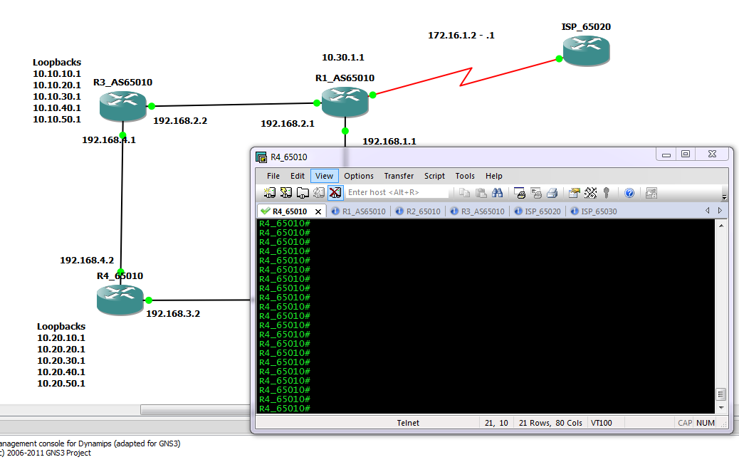
Well SecureCRT has a nice little feature to do this, so before enabled secure CRT looks much like below, as you can see I have several tabs open.

Default SecureCRT Window

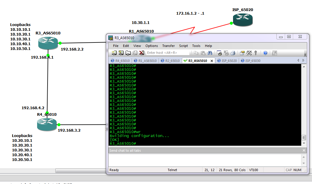
However by going in to the view menu up the top there is a option to enable the “chat window”, this will bring up an extra panel at the bottom of the screen. Then by right clicking in this new panel you can enable the “send chat to all tabs” option as shown below.

Chat window enabled

Now any command typed in the chat window will be sent to all devices. Commands typed in the main terminal are still only sent to a single device.

What would be even nicer is if you could highlight multiple tabs and have the commands only sent to those terminal sessions. At the moment it is an all or nothing solution, maybe I will go suggest it to them as an improvement for future versions 🙂

The more I use CRT the more I like it, written quite a few scripts for it now, if you know any VB script or Java you can pretty much do what ever you like as SecureCRT has a nice simple API in to it.

I am finally moving house this week, so after that should have more time to post on here, and will take some of the script I have and tidy them up and post them for people.

Take care

DevilWAH

Switch Vs Route

I see a lot of people as Questions such as what is harder the Switch or the Route exam, Or Why is the Route coarse materials so much larger than the Switch, does this mean there is less to it? 642-902 ROUTE  642-813 SWITCH

So having now completed both foundation and cert guides here are my views.

First the two have very different goals that they are trying to teach, and approach things in the same way as you would likely see in the Real world.  

ROUTE

In the real world generally Routing protocols stand apart, while you may run EIGRP and OSPF with in he same organisation, most people will keep them separate and they will only interact at the borders. And there are only 3/4 major routing protocals that you woudl expect to see.

RIP,

OSPF,

EIGRP and

BGP.

While there are others these are the common ones that most people will using there jobs. So the ROUTE exam deals with these along with redistributing the routes between them.

This give the following Topics to study

EIGRP
OSPF
BRP
Redistribution and Patch control
IPv6

And each is covered in some detail.

SWITCH

On the other hand has many more topics, and in the case of switch’s many of these will be run on the same devices across the entire network, (eg. VLANS, Spanning Tree, ACL’s Switch Security) so the number of topics in the SWITCH exam is much higher. They are covered in less depth individual than the topics in ROUTE, however you are expected to understand how they all work together and how issues configuring one can cause issues in others.

A partial list of topics covered in switch are.

VLANS
Switch Operation (CAM TCAM and other switch tables)
CEF
VLANS
STP (all modes)
STP enhancements like BPDU guard and ULD detection.
Ether channels and port channels
Multilayer switches
High availabilities (redundet router and redundant supervisors)
IP telephony
Wireless
Securing switch devices
Port security
ACL’s
Vlan ACL’s
Private VLANS
QOS
and the list goes on….

So the question of what one is hard and what one is easy will very much depend on the person taking them, and the current experience they have. Many people do seem to find the Routing exam nicer and I think this is because you can take each topic seperatly and concentrate with out worrying about the rest. While I enjoyed Switch as it was lots of bite size chunks to get stuck in to.

People also ask what one to take first, honestly I don’t think knowing either one will help learning the other one, as long as you have  a decent understanding of networks. Personal I would first go for the one you have most experience with, and get it under your belt first.

The only one I would suggest leaving till last is the Trouble Shoot as this assumes you have knowlage of both Switch and Route.

Using Syslog while Studying in GNS3 (or indeed and cisco Lab)

I have been getting back in to my studying a lot lately and one thing I have found is the need to use a lot of debug commands so I can watch what is happening during things like routing updates and neighbour formation. One thing I do find though is that I am forever having to turn debug on and off, forgetting to do one or the other, and when it is on it clutters up the screen a breaks up the config I am entering making it difficult to read back.

Which got me thinking, I have used syslog servers a lot in the past, so why not send all the debugging out put to a syslog server and turn of logging to the console? This way I can have all the debugs in one place, and keep the console of the devices tidy so I can see what I am doing.

Now if you are doing this through GNS3 you will need a cloud connection so your PC can talk to your GNS3 network. If you are not sure how to do this there are lots of videos and walk though on the net, however the one below is one of the best I have found, very clear and complete.

How-To: Using the Cloud in GNS3 to Provide Internet Access from Matthew on Vimeo.

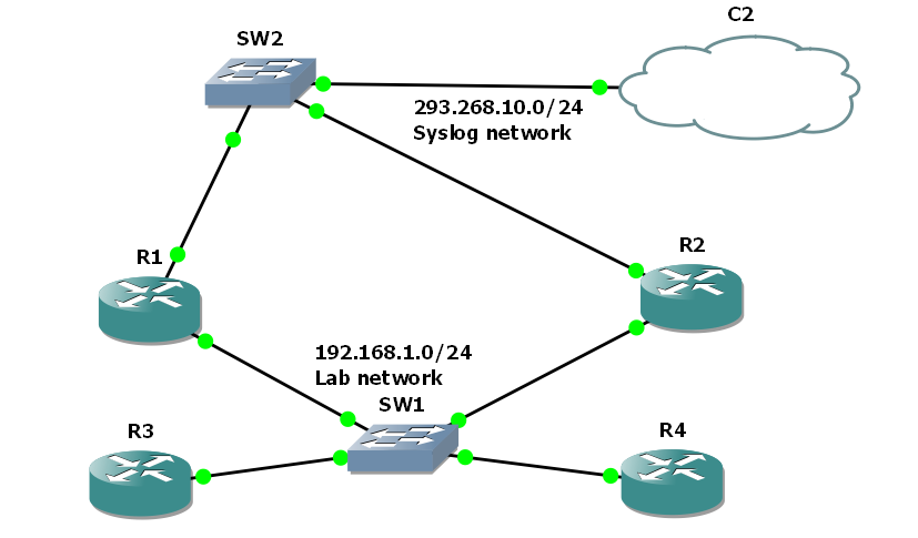
So once you have your cloud set up you then need to set up a simple GNS3 topology, Here I have set up 4 routers running OSPF connected through a switch as I am looking at the DR and BDR election process.

I have given R1 and R2 F0/1 address 192.168.10.10 and 192.168.10.20, and the loopback adapter used by the cloud is 192.168.10.254. Once the routers are booted and connected to the cloud, check they can ping the loop-back address (you may need to disable your fire wall on the loop-back connection.)

then of course you will need a SFTP server, in windows there are two good free choises, for a realy simple server that can run with out install try, http://tftpd32.jounin.net/tftpd32.html simple but does all you need, just make sure you disable dhcp and other none necessaries services in the settings. For a more complete tool try http://kiwisyslog.com/, they have a free syslog server offering that allows filtering and more.

In either case set it up and insure it is listing on the loopback interface, in the case of TFTP32d this is simple a case of choosing the interface from the drop down list.

Finale we need to change the logging setting of R1 and R2 to direct debugging message to the syslog server and not to the console. Remember debug messages are level 7 so we need to set console logging to level 6 or lower and trap logging to level 7. the following code will do just this from global config mode.

#logging 192.168.10.254
#logging console 6
#logging trap 7

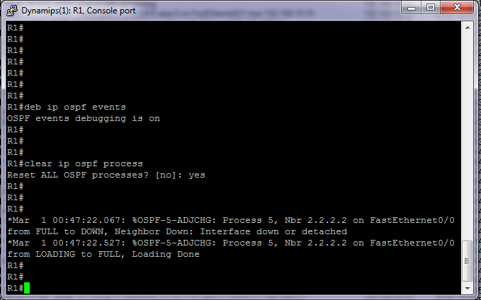
So now we can enable the debugging and reset the neighbour relation ships to see what it looks like.

From the console

So not much there apart from we see the neighbours bounce as I clear the OSPF process.

So how about on the syslog server?? 

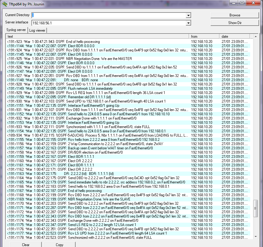
So here are all our debug messages, for us to scroll through and review at our leisure, If you have something like Kiwicat syslog server you could filer them in to views, based on device that sent it, or text with in message, ect.

You need to make sure of course that you either have the device connected directly to the syslog server network, or it has a route to get there. Directly connected is always best of course as you will insure that as long as that interface on the device is up you will catch all messages. On real hardware simply use a spare switch or create a separate VLAN and do exactly the same thing.

I have found for large labs this works great, indeed for testing setups for clients its great as well. once you have insured the correct debugging is enabled you can walk though test scripts and plans, safe in the knowledge that you have a full detailed log of every thing that has happened.

Simple to set up and hopefully some of you will find it useful.

DevilWAH

CCNP ROUTE (Part 10 EIGRP Over NBMA)

In what I think will be the last post on EIGRP (I will save redistribution between routing protocols for another time), I want to look at what is needed to insure EIGRP runs smoothly over NBMA (non broadcast multi access) networks such as Frame Relay.

As I have covered before EIGRP relies on multicast hello messages to form its neighbour relationships, but NBMA network by default do not forward any broadcast or multicast traffic. So this is the first issue with getting it up and running.

To achieve this you have two choices. First you could if you wished manually set up the neighbours. Going under the EIGRP AS process you can issues the command

router#(config-router)#neighbor <IP ADDRESS>  <INT ID>

This need to be done on both ends of the link, and will change the interface from sending out multicast hello messages to directed broadcasts, so you need to enter addition neighbour statements for each neighbour you want to connect to.

For some NBMA networks (such as frame relay) CISCO has added in a command to allow the router to forward the broadcasts over the link. It does this by sending a copy of the multicast/broadcast packet to each neighbouring router. This is needed for multipoint networks

#router(config-inf)#frame-relay  map IP <neighbour IP>  <Local DLCI>  broadcast

Now rather than using the neighbour command the router will forward any EIGRP hello’s across the to any routers configured with the broadcast command in there mapping.

Either of these two methods will allow the formation across the NBMA.

However there’s is now the issue of split horizon. Imagen you have a central router connected to two remote routers, each with there own routing tables. Split horizon says that a route update received on an interface will not be sent back out that same interface.  This means that if one of the remote routers sends an update to the central router, it will not then be relayed over to the second remote router.. To allow this to happen you must manually disable split horizon (it is disabled by default on a physical interface but enabled on sub interfaces). The command is as follows

router(config-inf)#no ip split-horizon eigrp <AS>

So recapping there is two parts to this, first allowing the hello messages across the NBMA, and then insuring the updates get copied to all routers.

These problems mainly occur when using the multipoint method, using point to point (although requiring more IP addresses and subnetting) avoids both the split horizon issue and the non broadcast issues, and is generally the recommended option.

DevilWAH

Simulating PC’s in GNS3

One of my main issues with GNS3 for studying that there are no end devices (PC’s) by default. Ok you can set up loopback interfaces, or add in an extra router and just configure one interface with an IP to act an an end device. But loopbacks don’t really show well when looking at the topology on screen, and adding a whole router (or creating a Qemu host) seems to be a bit much when all you need is a device that can reply to and send pings and/or run trace routes.

However the other day I came across VPCS! There is actuly a down load for this at the bottom of the GNS3 site (here), and it is so simple and easy to get up and running that I suggest any one who uses GNS3 has a look.

Simple unpack the zip file to a folder and then run the VPCS.exe file. this will by default create 3 PC’s with various IP addresses. However it is simple to configure it to create up to 9 separate simulated PC’s with either static or DHCP assigned addresses. These can then be easily added to GNS3 topologies by adding a cloud (see later in the post for how to make them look pretty), and configuring a NIO_UDP port. Really it takes all of 10 seconds to get it up and running. Then you have a simple CLI interface to the “virtual PC’s” where you can run Pings and Traceroutes.

There is only one thing to be careful of. You may find the cygwin1.dll file is a different version in GNS3 as to the version that comes with VPCS and this can casue issues. I find the simple way around this is to delete the cygwin1.dll file from the VPCS folder, and then copy the one form the GNS3 program folder in. (even better copy it to a system path such as c:\window\system32, and then delete it from both folders, and just keep a single copy they both can use).

The following is a link to a blog post on www.firstdigest.com with a video tutorial of how to set it up. (GNS3 and VPCS Video)

Now your GNS3 topology’s can actuly look and run like proper topologies and with our the overheads of emulating entire routers of operating systems. OK if you really need more complex hosts then there are other ways to do that, but for simple end devices that can ping and be pinged it is GREAT!!

DevilWAH

CCNP ROUTE (Part 9 EIGRP Authentication)

Seeing as we just finished up a simple EIGRP lab, it seems a good opportunity to add one more simple thing in to the mix.

At the moment any one could in theory add a router in to the network, sniff for packets to determined the AS number we are running EIGRP on, and start advertising routes and forming neighbours. This is not something we want to happen, even if not a malicious attack a rogue router sending EIGRP hellos and updates could cause havoc with a network.

So like all good network administrators it is important to secure EIGRP against such happenings. This is achieved in EIGRP by means of md5 authentication and key-chains.

The theory works some thing like this. All routers must be in time with each other, if possible a time protocol such as NTP should be used, but you could also set the clocks manually (just remember to redo this after a reboot as the router will lose its time). One they are in sync we can set up the key-chains. Each key chain has a number, time frame in which it will be sent and a time frame in which it will be accepted, along with the actual key value its self.

For a key to be accepted as valid by a router, when it receives it, the key-chain number and the key value must match on both devices, and it must be revived with in the accepted time frame. Below is a generic template for setting up a key-chain.

Router(config)#key chain
Router(config-keychain)#key
Router(config-keychain-key)#key
Router(config-keychain-key)#send-lifetime
Router(config-keychain-key)#accept-lifetime

The idea is that you may use one key each month for example, with the accept and send time of the next key in the chain over lapping with the last slightly (if you have NTP the over lap can be a matter of seconds due to the increased sync of the routers clocks), to insure the neighbours do not get dropped during the change over of keys.

Once the keys have been set up you apply them to the interface which is sending out EIGRP updates as below.

interface FastEthernet0/0
 ip authentication mode eigrp <AS> md5
 ip authentication key-chain eigrp <AS> <keychain name>

I have set this up in the GNS3 lab here.. to get it working you will need to set the time on router 1 to 00:00:00 24th october 2010 (#clock set 00:00:00 24 october 2010), and then on router 2 remove and re-add the NTP server. This will sync up the clocks to the correct time for the configured key chains. You should then see the neighbours come up. Running a #Debug eigrp packets, and you will see the hellos and updated getting sent with the md5 authentication.

DevilWAH

CCNP ROUTE (Part 8 EIGRP Simple Lab)

I decided that rather than just use other people labs I would come up with a few of my own, the following lab is very simple, requiring the enabling of EIGRP on two routers so they form a neighbour relation ship, and setting up which routes will be advertised. Followed by some simple summarization to reduce the size of the routing tables.

You can find the GNS 3 topology files HERE, these also contain the finalised configs if you want to see the method and commands used. (note you will need a 2691 image installed)
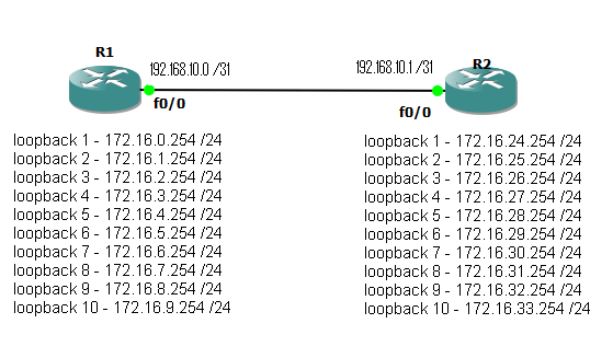
Fig 1

To start with we have two routers connected via a point to point link on interface Fastethernet 0/0. Each also has 10 loop back interfaces configured with various /24 networks configured.

The aim is simple, enable EIGRP with an AS number of 10, form a neighbour relationship between the two routers and update the routing tables so both routers can see / reach all configured networks. Ideal use as few network statements as possible, while remaining as specific as possible as to what networks get advertised. Autosmmorization should also be disabled.

After completing this, a #show ip route, should display something like this.

router1#sh ip route
Codes: C - connected, S - static, R - RIP, M - mobile, B - BGP
D - EIGRP, EX - EIGRP external, O - OSPF, IA - OSPF inter area
N1 - OSPF NSSA external type 1, N2 - OSPF NSSA external type 2
E1 - OSPF external type 1, E2 - OSPF external type 2
i - IS-IS, su - IS-IS summary, L1 - IS-IS level-1, L2 - IS-IS level-2
ia - IS-IS inter area, * - candidate default, U - per-user static route
o - ODR, P - periodic downloaded static route

Gateway of last resort is not set

192.168.10.0/31 is subnetted, 1 subnets
C       192.168.10.0 is directly connected, FastEthernet0/0
172.16.0.0/24 is subnetted, 20 subnets
D       172.16.32.0 [90/409600] via 192.168.10.1, 00:01:01, FastEthernet0/0
D       172.16.33.0 [90/409600] via 192.168.10.1, 00:01:01, FastEthernet0/0
D       172.16.28.0 [90/409600] via 192.168.10.1, 00:01:01, FastEthernet0/0
D       172.16.29.0 [90/409600] via 192.168.10.1, 00:01:01, FastEthernet0/0
D       172.16.30.0 [90/409600] via 192.168.10.1, 00:01:01, FastEthernet0/0
D       172.16.31.0 [90/409600] via 192.168.10.1, 00:01:01, FastEthernet0/0
D       172.16.24.0 [90/409600] via 192.168.10.1, 00:01:01, FastEthernet0/0
D       172.16.25.0 [90/409600] via 192.168.10.1, 00:01:01, FastEthernet0/0
D       172.16.26.0 [90/409600] via 192.168.10.1, 00:01:01, FastEthernet0/0
D       172.16.27.0 [90/409600] via 192.168.10.1, 00:01:01, FastEthernet0/0
C       172.16.8.0 is directly connected, Loopback9
C       172.16.9.0 is directly connected, Loopback10
C       172.16.4.0 is directly connected, Loopback5
C       172.16.5.0 is directly connected, Loopback6
C       172.16.6.0 is directly connected, Loopback7
C       172.16.7.0 is directly connected, Loopback8
C       172.16.0.0 is directly connected, Loopback1
C       172.16.1.0 is directly connected, Loopback2
C       172.16.2.0 is directly connected, Loopback3
C       172.16.3.0 is directly connected, Loopback4

Now to reduce the size of the routing table we can manually summarise the routes. This is carried out under the interface that is sending out the update (in this case it will be fast ethernet 0/0 on each router). Again we want to be as specific as possible. The completed LAB uses multiply summarization statements , this increase the specificity of the summarization at the expense of adding an extra route in to the table. The routing table should now look something like.

router2#sh ip route
Codes: C - connected, S - static, R - RIP, M - mobile, B - BGP
D - EIGRP, EX - EIGRP external, O - OSPF, IA - OSPF inter area
N1 - OSPF NSSA external type 1, N2 - OSPF NSSA external type 2
E1 - OSPF external type 1, E2 - OSPF external type 2
i - IS-IS, su - IS-IS summary, L1 - IS-IS level-1, L2 - IS-IS level-2
ia - IS-IS inter area, * - candidate default, U - per-user static route
o - ODR, P - periodic downloaded static route

Gateway of last resort is not set

 192.168.10.0/31 is subnetted, 1 subnets
C       192.168.10.0 is directly connected, FastEthernet0/0
172.16.0.0/16 is variably subnetted, 15 subnets, 2 masks
C       172.16.32.0/24 is directly connected, Loopback9
D       172.16.32.0/21 is a summary, 00:02:27, Null0
C       172.16.33.0/24 is directly connected, Loopback10
C       172.16.28.0/24 is directly connected, Loopback5
C       172.16.29.0/24 is directly connected, Loopback6
C       172.16.30.0/24 is directly connected, Loopback7
C       172.16.31.0/24 is directly connected, Loopback8
C       172.16.24.0/24 is directly connected, Loopback1
D       172.16.24.0/21 is a summary, 00:02:28, Null0
C       172.16.25.0/24 is directly connected, Loopback2
C       172.16.26.0/24 is directly connected, Loopback3
C       172.16.27.0/24 is directly connected, Loopback4
D       172.16.8.0/24 [90/409600] via 192.168.10.0, 00:02:26, FastEthernet0/0
D       172.16.9.0/24 [90/409600] via 192.168.10.0, 00:02:26, FastEthernet0/0
D       172.16.0.0/21 [90/409600] via 192.168.10.0, 00:02:26, FastEthernet0/0

So the routes from Router 1 are now summarized in to 3 blocks. 172.16.0.0/21 which would include the first 8 networks, plus the 172.16.8.0 and 172.16.9.0 /24 which fall out side the summarization.

Note also the routes to null that have been entered. When you set up a summarization, the router will automatically set up a route to null for that network. The reason for this is that you many not actually have routes to all the subnets for the network you have advertised as a summary. Imagen in the above case there was no loop back 5 and 6 on router 2, so no networks 172.16.28.0 and 172.16.29.0 /24. But the router is still advertising a summary address that includes them. When packet arrive at the router they are routed based on the most specific match. so a packet coming in with a destination address of 172.16.27.59 will match both the following routes.

D 172.16.24.0/21 is a summary, 00:02:28, Null0
C 172.16.26.0/24 is directly connected, Loopback

but because /24 is more specific than /21 the route to the loop back interface will be used. However if there is no more specific route, then the null route will be matched and the packets discarded.

OK I said it was simple and it is. The topology files have both the starting position and my completed example. This is of course not the only solution. You can argue there are neater ways to do it, but I chose to use multiply statements to show how specific networks can be picked and what happens when summary address do not exactly match the networks that are configured.

There will be one more EIGRP Lab coming up that will be more involved and included redistribution of static routes and manual formation on neighbours.

DevilWAH

CCNP ROUTE (Part 7 EIGRP General commands)

OK so been reading the intro to EIGRP, now its time to get configuring,  I think the best way to remember these is to take each one in turn and describe its function. Starting with the global commands, then the EIGRP specific commands, followed by some of the interface commands, and ending with a few basic verification commands. (For this post the configured name of the router will be “R1”)

GLOBAL COMMANDS.

R1(config)#ip routing.

This command is enabled by default on routers and disabled on layer 3 switches (some newer IOS do seem to have it enabled). Running this command enables routing on the device, with out it no routing of any kind will be preformed by the switch.

R1(config)#ip route <ip address> <subnet mask> <next hop address>

This command set a static route entry, not strictly EIGRP but important enough to know to be here. The next hop address can by an ip address to forward the traffic to, or jsut the interface to send the traffic out. It is considered best practice to if possible specify an ip address if possible. One common route entered this way is the “default route”

R1(config)#ip route 0.0.0.0 0.0.0.0 &lt;next hop address / interface&gt;

This sets the destination to pass all unknown traffic to, traffic that there is no specific entry in the routing table for.

R1(config)#router eigrp <AS number>

Enters into the eigrp configuration mode for the stated AS number, all routers running eigrp that are so share routing table/information, must be running the same AS number. If this is different then routers will not form neighbour relationships.

R1(config)#router eigrp 10

EIGRP CONFIGURATION MODE

R1(config-router)#auto-summary

By default this command is set to be enabled (although I believe in IOS version 15 is is now defaulted to “no auto-summery”). Having it enabled will cause EIGRP to automatically summarise all routes to their class full boundaries. Most people will want to diable this to give more control and manage summarization manually.

R1(config-router)#network <ip address> <wildcard mask>

This command has two separate effects. First it will enable the sending of routing update out of any interface that matches the address and wild card mask. Secondly it will advertise the networks that those interfaces have assigned to them. if for example you have the interface with the following ip address and subnet mask assigned. 192.168.5.254 255.255.255.0. and you add the eigrp network command.

R1(config-router)#192.168.5.254 255.255.255.255 (only the single ip address)

eigrp will send out updates on that interface, but these will included the advertised route 192.168.5.0 / 24, as this is the network subnet assigned to the interface.

R1(config-router)#Passive interface <int ID / Default>

Image you run the last command (network x.x.x.x y.y.y.y) on  the IP range for an interface that is connected to an end users network, with no other routers to form neighbours with? In this case you most likley do not want to send out routing updates but you still wish to advertise the network. In this case you can run the passive interface command to prevent multicast hello and update messages getting sent out.

R1(config-router)#neighbour <IP address> <interface ID>

Now Imagen you have run the passive interface command, but you wish to still send and receive updates from and two specific routers out of that interface? Using the neighbour command allows you to do this. In fact setting a neighbour in this method effectively turns the interface in to a passive interface by changing the hello messages from using the multicast address, to using unicast addresses.

INTERFACE CONFIGURATION MODE.

R1(config-if)#ip summary-address eigrp <AS num> <ip> <subnet mask>

If you have disabled auto-summary in the eigrp config mode, you may still want to do manual summarization. Configured under an interface, this command will summarize all routes that are advertised out that interface and that fall in to the summary network specified in to a single routing advertisment. Multiply summary address can be configured per interface, to cover multiply summary routes.

OK so that’s some of the eigrp commands to get started with. There are of course many more but using these it is possible to enable eigrp, configure the networks to be advertised (and what interfaces to advertise them on), and form neighbour relationships that will populate the routers routing table. So then the questions becomes how do we tell if it is all working

VERIFY COMMANDS

R1#show ip route

This will display the current routing table that has been populated by all routing protocols running, plus static routes and connected networks, that is used by the router to make decisions on the actually forwarding of data packets.

R1#show ip eigrp neighbours

Displays details about the neighbours EIGRP knows about. (neighbour table)

R1#Show ip eigrp topology

Show details of all networks that EIGRP has learnt about, details of how to reach them and what neighbours have advertised them. things like which one is the successor and feasible successors are shown here. This is a display of the topology table.

Now this table is not complete, so look out for part 2 to this table for when we get on to redistribution and more complex EIGRP setups.

DevilWAH