CCNP SWITCH EXAM

Well I was going through emails a few weeks back and came across an email for cisco with an exam voucher for the switch exam. (from back last year when the exam crashed on me). Checking it out the date was 17th march!!! (today).

With new job and baby, i havent had much time to study, as the lack of posts should tell you. But rather than wast the voucher i booked the exam and dusted of the books. After 2 weeks of sporic studying i sat the exam.

I think i might of actuly punched the air when i saw i passed at the end!!! And actuly with a half decent score.

But even better I now feel like i have the bug again, work has taken me in a slightly different direction. Still network but managment and not quite as hands on. Time to change that I and get CCNP done and dusted.

Hope that will also mean more posts as well. 🙂

Take care all

DevilWAH

A bit of perl while I’ve been away (Always including some CISCO of course).

Well no matter how many times I head back to post just lately I have never had the time. Studying been put on hold, house move on hold, and working falt out at the new job, but I have to say it has been fun.

Like I say not much studying done, but I have been playing with perl scripting latley. So rather than post nothing I thought I would share the results with you.

At work one of my teams jobs is to provision ports and reclaim ports on switchs. we basicaly write scritps during the day and then batch implement at night. So to make things a bit simpler, (and casue I was bored) I wrote a little web page using perl scripting as the back end.

Now I know I could use client side scripting to get a neater effect, and / or a stand alone program. But one thing about this was I wanted it as client friendly as possible, so decided to go for a web interface. And I have been meaning to learn a scripting language for ages so this seemed an good opportunity.

The web page is in two parts, one for provisioning ports and a second for reclaims, both can handle CATOS and IOS configs

They both still need some tidying up and I want to add some better functions to them soon, but Just so you don’t think i have disappeared here’s the link is you want to try them out. 🙂 (they link to each other)

Port provisioning script

The reason it is set out as it is, is that for my job servers are duel link to two switch, so for each script we are provisioning 3 or 5 ports per server mostly. Also the second switch is normally a mirror of the first, so by ticking the copy check box you only then need to fill in the interface on the second switch, the vlan, speed, duplex, ilo (integrate lights out for use when server crashes to remote reboot and get access to the bios) and sub-net information will be copied from the first switch. Port description as set to the name of the server configured.

I want to put some error checking in the webpage so users can’t skip filling in fields, and then expand to allow users to alter the number of switch / interfaces on the fly.

But for now it seems to work OK, and definitely speeds up or scripting tasks.

Let me know what you think 🙂 If you have any suggestions or would like to see the source code let me know. If you wold like a bit more in depth of what I did may be i can do a follow up artical at some point.

Cheers

DEVILWAH.

PS. little baby is doing great. 9 months old and I finaly understand what people mean when the say how life changing having a baby is! Miss Lilith as she is know in our house is laughing smiling and generaly making my life great. Can’t wait for the warm weather to take her out more 🙂

Spanning Tree enhancements (Backbone Fast)

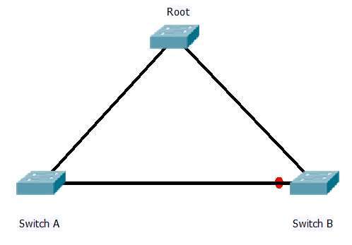
Last time I look at the spanning tree enhancment I covered uplink fast, this is for detecting when a directly connected root port fails and switching over to a back up in the shortest time possible. But what happens if the link that fails is not directly connected. When a switch loses its link back to the root and needs to find an alternate path back. In the digram below switch B is blocking its port to Switch A to prevent loops.

The question is what happens if the link between Switch A and the Root fails? Well with out backbone fast the following sequince takes place.

When the link fails Switch A will no longer be receiving BPDU’s from the root, the direct link is down and the port on switch B is blocking so not forwarding BPDU’s.

Switch A will assume it is the new root and start to send BPDU’s towards Switch B declaring it is the root. However Switch B will see these are inferior BPDU’s to the on it has stored for the port connected to Switch A and ignore them.

This will continue to happen until the BPDU on the port times out, after which the port will go in to the listing and learning state before starting to forward. This is 20 seconds (max age timer) plus 2 x 15 seconds for the listing and learning stage. so a total of 50 seconds.

The idea behind Backbone fast is to cut this by 20 seconds by bypassing the max age timer. The idea is that if Switch B can confirm it still has a link back it’s current known root switch, then it can ignore the max age timer and start the listing and learning process on a port immidatly it receives a inferior BPDU.

Once backbone fast is enabled, when a switch receives a inferior BPDU on one of its ports, it will send a RLQ (root link query) packet out all it’s non designated ports including its root port (so all ports that lead back to the root). If it receives a RLQ response (these are sent from the bridge) then it knows it still has a link to root. It can then age out the port it is receiving the inferior BPDU’s on and start the listing learning stages. If it does not receive any responses then the switch has lost connectivity to the rest of the network and needs to start recomputing the whole STP.

Either way the max age time has been eliminated and 20 seconds have been shaved of the re convergence / fail over time.

Just like Uplink fast Backbone fast is configured on a switch level with the following command.

Switch(config)#spanning-tree backbonefast

and it needs to be configured on all switches on the network.

CISCO’s document HERE explains it in much more details and more examples.

DevilWAH

CCNP ROUTE (Part 10 EIGRP Over NBMA)

In what I think will be the last post on EIGRP (I will save redistribution between routing protocols for another time), I want to look at what is needed to insure EIGRP runs smoothly over NBMA (non broadcast multi access) networks such as Frame Relay.

As I have covered before EIGRP relies on multicast hello messages to form its neighbour relationships, but NBMA network by default do not forward any broadcast or multicast traffic. So this is the first issue with getting it up and running.

To achieve this you have two choices. First you could if you wished manually set up the neighbours. Going under the EIGRP AS process you can issues the command

router#(config-router)#neighbor <IP ADDRESS>  <INT ID>

This need to be done on both ends of the link, and will change the interface from sending out multicast hello messages to directed broadcasts, so you need to enter addition neighbour statements for each neighbour you want to connect to.

For some NBMA networks (such as frame relay) CISCO has added in a command to allow the router to forward the broadcasts over the link. It does this by sending a copy of the multicast/broadcast packet to each neighbouring router. This is needed for multipoint networks

#router(config-inf)#frame-relay  map IP <neighbour IP>  <Local DLCI>  broadcast

Now rather than using the neighbour command the router will forward any EIGRP hello’s across the to any routers configured with the broadcast command in there mapping.

Either of these two methods will allow the formation across the NBMA.

However there’s is now the issue of split horizon. Imagen you have a central router connected to two remote routers, each with there own routing tables. Split horizon says that a route update received on an interface will not be sent back out that same interface.  This means that if one of the remote routers sends an update to the central router, it will not then be relayed over to the second remote router.. To allow this to happen you must manually disable split horizon (it is disabled by default on a physical interface but enabled on sub interfaces). The command is as follows

router(config-inf)#no ip split-horizon eigrp <AS>

So recapping there is two parts to this, first allowing the hello messages across the NBMA, and then insuring the updates get copied to all routers.

These problems mainly occur when using the multipoint method, using point to point (although requiring more IP addresses and subnetting) avoids both the split horizon issue and the non broadcast issues, and is generally the recommended option.

DevilWAH

Simulating PC’s in GNS3

One of my main issues with GNS3 for studying that there are no end devices (PC’s) by default. Ok you can set up loopback interfaces, or add in an extra router and just configure one interface with an IP to act an an end device. But loopbacks don’t really show well when looking at the topology on screen, and adding a whole router (or creating a Qemu host) seems to be a bit much when all you need is a device that can reply to and send pings and/or run trace routes.

However the other day I came across VPCS! There is actuly a down load for this at the bottom of the GNS3 site (here), and it is so simple and easy to get up and running that I suggest any one who uses GNS3 has a look.

Simple unpack the zip file to a folder and then run the VPCS.exe file. this will by default create 3 PC’s with various IP addresses. However it is simple to configure it to create up to 9 separate simulated PC’s with either static or DHCP assigned addresses. These can then be easily added to GNS3 topologies by adding a cloud (see later in the post for how to make them look pretty), and configuring a NIO_UDP port. Really it takes all of 10 seconds to get it up and running. Then you have a simple CLI interface to the “virtual PC’s” where you can run Pings and Traceroutes.

There is only one thing to be careful of. You may find the cygwin1.dll file is a different version in GNS3 as to the version that comes with VPCS and this can casue issues. I find the simple way around this is to delete the cygwin1.dll file from the VPCS folder, and then copy the one form the GNS3 program folder in. (even better copy it to a system path such as c:\window\system32, and then delete it from both folders, and just keep a single copy they both can use).

The following is a link to a blog post on www.firstdigest.com with a video tutorial of how to set it up. (GNS3 and VPCS Video)

Now your GNS3 topology’s can actuly look and run like proper topologies and with our the overheads of emulating entire routers of operating systems. OK if you really need more complex hosts then there are other ways to do that, but for simple end devices that can ping and be pinged it is GREAT!!

DevilWAH

Spanning Tree enhancements (Uplink fast)

In my last job, I jumped straight in to configuring Rapid spanning Tree, I mean what is the point of running Standard STP with its 50second fail over times, when you can enable Rapid-STP and gain sub second fail over??

Well if you want to pass your CCNP SWITCH you need to know it, and you need to know how to configure the enhancements. Actually having read through them and labed them up. They do help in understanding how STP works and how the original protocol was improved in a number of way, before CISCO took all the enhancements and came up with Rapid-STP.

Over the next few post I will be covering all of the basic enhancements, including uplinkfast, backbone fast, portfast, loopguard etc..

Uplinkfast.

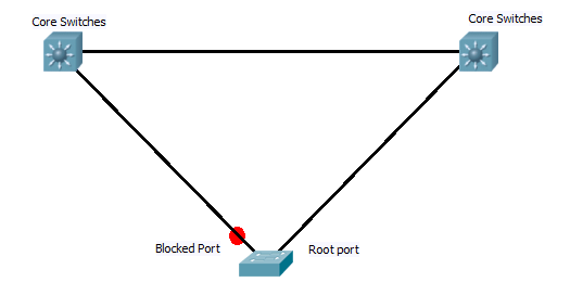
This is normaly configured on access switchs that have two links back to the root, in these cases after the initial STP algrothem has run, one of the ports (lowest priority back to the root bridge) will be designated as the root port, while the other will be blocked. See digram below.

Now with standard STP, if the active link fails, the switch sees the root port link has fail and as it is receiving root BPDU’s on the backup blocked port it starts to bring this up. However with out uplink fast enabled this requires the port to go through the listening and learning stages. By default this is 30 seconds of outage, and even with best STP tuning it still results in a 14 second outage.

However with uplink fast configured the switch keeps track of the blocked ports that point back to bridge and forms them in to an “uplink group”. Now if the primary link goes down the switch can pick the next best root port and immediately places it in the forwarding mode as this will not be creating a loop. This creates an almost instant fail over of the primary link. However switch CAM tables will now be out of sync, which could result in frames being sent down the wrong links. To sort this out, the switch creates dummy frames with source address from its CAM table, and destination of multicast address. this updates the other switches on the network.

Now when the link comes back up, the switch waits twice the forward delay + 5 seconds before it switches back over. This allows the core switch at the other end of the link to have time to run through STP and start forwarding on the port.

And that’s Uplink fast. Providing a method to allow instant fail over of directly redundant links towards the root.

Configuration is very simple and is carried out in global config mode.

Switch(config)Spanning-tree uplinkfast

DevilWAH

Upgrading Redundant Supervisors on 6500’s

I need to know how to upgrade the IOS on CISCO 6500’s, So here is the outline along with a download of the official PDF from CISCO.

First confirm what IOS image is running, which supervisor is running as active and the redundancy mode that is active. This can be achieved with the following commands.

Router#show version
Router#show module
Router#show redundancy 

You should now know the current IOS version and the module numbers of the supervisor units and which one is active.
Now we need to set up the boot variable (so the correct IOS boots) and copy the new IOS over if necessary.

Router#show bootvar  (Find out the current IOS booting)

Router#copy start tftp (copy the current start up configuration to TFTP for safe keeping)

Router#copy tftp disk0:          (Copy the new IOS to the two supervisors)
Router#copy tftp slavedisk0:

Router#no boot system disk0:old_IOS.bin
Router#boot system disk0:new_IOS.bin   (set up the new boot variable on the active supervisor)

Router#copy run start  (syncs running configuration on both supervisor units)

Now the boot variables are set up and the new IOS images are on the supervisors we can upgrade each in turn, starting with the one currently set as the standby.

Router#hw-module module  reset  (chose standby supervisor to reset)

Standby supervisor will now reboot and restart running the new IOS image. During this time the redundancy mode will fall back to RPR mode due to the mismatch in IOS images running. You can see this by running the “show” commands above.

Once the standby is fully back up and running you can now update the active module, this is done by forcing the standby to become active, this will result in a reload of the current active supervisor.

Router#redundancy force-switchover (switches standby to become active and reloads current active)

(you will need to swap console cables over to the standby supervisor as only the currently active one can be consoled in to.)

Again use the above “show” commands to check the modules have reloaded correctly, both supervisors are running the same IOS version, and the correct redundancy method. Now the original active router will be the standby. If you wish you apply the last command above to force a second switch over back to the original.

And there it is, upgrade of IOS with out taking the switch off line. Although it is suggested it is done out of hours as there may be some minor traffic interruptions during the switch over.

Here is the CISCO PDF, with more detail and outputs of the commands..

DevilWAH

CCNP ROUTE (Part 9 EIGRP Authentication)

Seeing as we just finished up a simple EIGRP lab, it seems a good opportunity to add one more simple thing in to the mix.

At the moment any one could in theory add a router in to the network, sniff for packets to determined the AS number we are running EIGRP on, and start advertising routes and forming neighbours. This is not something we want to happen, even if not a malicious attack a rogue router sending EIGRP hellos and updates could cause havoc with a network.

So like all good network administrators it is important to secure EIGRP against such happenings. This is achieved in EIGRP by means of md5 authentication and key-chains.

The theory works some thing like this. All routers must be in time with each other, if possible a time protocol such as NTP should be used, but you could also set the clocks manually (just remember to redo this after a reboot as the router will lose its time). One they are in sync we can set up the key-chains. Each key chain has a number, time frame in which it will be sent and a time frame in which it will be accepted, along with the actual key value its self.

For a key to be accepted as valid by a router, when it receives it, the key-chain number and the key value must match on both devices, and it must be revived with in the accepted time frame. Below is a generic template for setting up a key-chain.

Router(config)#key chain
Router(config-keychain)#key
Router(config-keychain-key)#key
Router(config-keychain-key)#send-lifetime
Router(config-keychain-key)#accept-lifetime

The idea is that you may use one key each month for example, with the accept and send time of the next key in the chain over lapping with the last slightly (if you have NTP the over lap can be a matter of seconds due to the increased sync of the routers clocks), to insure the neighbours do not get dropped during the change over of keys.

Once the keys have been set up you apply them to the interface which is sending out EIGRP updates as below.

interface FastEthernet0/0
 ip authentication mode eigrp <AS> md5
 ip authentication key-chain eigrp <AS> <keychain name>

I have set this up in the GNS3 lab here.. to get it working you will need to set the time on router 1 to 00:00:00 24th october 2010 (#clock set 00:00:00 24 october 2010), and then on router 2 remove and re-add the NTP server. This will sync up the clocks to the correct time for the configured key chains. You should then see the neighbours come up. Running a #Debug eigrp packets, and you will see the hellos and updated getting sent with the md5 authentication.

DevilWAH

CISCO commands

Just lately while cleaning up things at work, and on the web I have come across some CISCO commands that are usefully but often over looked, or forgotten. So I thought I would write them up here and attach them to the Tips and Tricks page so I would always have them to hand. IT might start of a small list but I hope to increase it gradually as I remember/find more. Think of it as a work in progress which you can find here.

I also though as well as the useful ones I would create a common list as well. These are things like the #show IP interface brief, and show Interface status. Again a work in progress and found under the tips and tricks page. If you have any ides suggestions for things that should be included let me know.

I don’t want to have a list of every command on CISCO, but the common ones we all use daily and take for granted. Or ones that are not quite so well known but very useful nevertheless

As I say the lists are no way completed, but I have put up the pages so I can start adding thing on, as and when I think of them.

DevilWAH