Simulating PC’s in GNS3

One of my main issues with GNS3 for studying that there are no end devices (PC’s) by default. Ok you can set up loopback interfaces, or add in an extra router and just configure one interface with an IP to act an an end device. But loopbacks don’t really show well when looking at the topology on screen, and adding a whole router (or creating a Qemu host) seems to be a bit much when all you need is a device that can reply to and send pings and/or run trace routes.

However the other day I came across VPCS! There is actuly a down load for this at the bottom of the GNS3 site (here), and it is so simple and easy to get up and running that I suggest any one who uses GNS3 has a look.

Simple unpack the zip file to a folder and then run the VPCS.exe file. this will by default create 3 PC’s with various IP addresses. However it is simple to configure it to create up to 9 separate simulated PC’s with either static or DHCP assigned addresses. These can then be easily added to GNS3 topologies by adding a cloud (see later in the post for how to make them look pretty), and configuring a NIO_UDP port. Really it takes all of 10 seconds to get it up and running. Then you have a simple CLI interface to the “virtual PC’s” where you can run Pings and Traceroutes.

There is only one thing to be careful of. You may find the cygwin1.dll file is a different version in GNS3 as to the version that comes with VPCS and this can casue issues. I find the simple way around this is to delete the cygwin1.dll file from the VPCS folder, and then copy the one form the GNS3 program folder in. (even better copy it to a system path such as c:\window\system32, and then delete it from both folders, and just keep a single copy they both can use).

The following is a link to a blog post on www.firstdigest.com with a video tutorial of how to set it up. (GNS3 and VPCS Video)

Now your GNS3 topology’s can actuly look and run like proper topologies and with our the overheads of emulating entire routers of operating systems. OK if you really need more complex hosts then there are other ways to do that, but for simple end devices that can ping and be pinged it is GREAT!!

DevilWAH

Spanning Tree enhancements (Uplink fast)

In my last job, I jumped straight in to configuring Rapid spanning Tree, I mean what is the point of running Standard STP with its 50second fail over times, when you can enable Rapid-STP and gain sub second fail over??

Well if you want to pass your CCNP SWITCH you need to know it, and you need to know how to configure the enhancements. Actually having read through them and labed them up. They do help in understanding how STP works and how the original protocol was improved in a number of way, before CISCO took all the enhancements and came up with Rapid-STP.

Over the next few post I will be covering all of the basic enhancements, including uplinkfast, backbone fast, portfast, loopguard etc..

Uplinkfast.

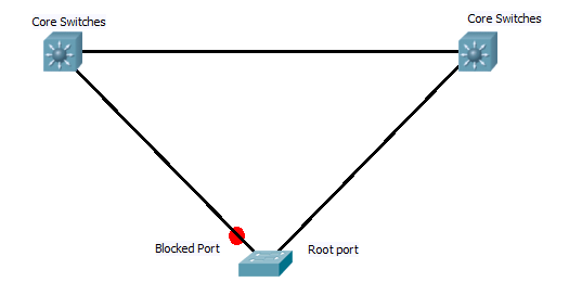
This is normaly configured on access switchs that have two links back to the root, in these cases after the initial STP algrothem has run, one of the ports (lowest priority back to the root bridge) will be designated as the root port, while the other will be blocked. See digram below.

Now with standard STP, if the active link fails, the switch sees the root port link has fail and as it is receiving root BPDU’s on the backup blocked port it starts to bring this up. However with out uplink fast enabled this requires the port to go through the listening and learning stages. By default this is 30 seconds of outage, and even with best STP tuning it still results in a 14 second outage.

However with uplink fast configured the switch keeps track of the blocked ports that point back to bridge and forms them in to an “uplink group”. Now if the primary link goes down the switch can pick the next best root port and immediately places it in the forwarding mode as this will not be creating a loop. This creates an almost instant fail over of the primary link. However switch CAM tables will now be out of sync, which could result in frames being sent down the wrong links. To sort this out, the switch creates dummy frames with source address from its CAM table, and destination of multicast address. this updates the other switches on the network.

Now when the link comes back up, the switch waits twice the forward delay + 5 seconds before it switches back over. This allows the core switch at the other end of the link to have time to run through STP and start forwarding on the port.

And that’s Uplink fast. Providing a method to allow instant fail over of directly redundant links towards the root.

Configuration is very simple and is carried out in global config mode.

Switch(config)Spanning-tree uplinkfast

DevilWAH

Upgrading Redundant Supervisors on 6500’s

I need to know how to upgrade the IOS on CISCO 6500’s, So here is the outline along with a download of the official PDF from CISCO.

First confirm what IOS image is running, which supervisor is running as active and the redundancy mode that is active. This can be achieved with the following commands.

Router#show version
Router#show module
Router#show redundancy 

You should now know the current IOS version and the module numbers of the supervisor units and which one is active.
Now we need to set up the boot variable (so the correct IOS boots) and copy the new IOS over if necessary.

Router#show bootvar  (Find out the current IOS booting)

Router#copy start tftp (copy the current start up configuration to TFTP for safe keeping)

Router#copy tftp disk0:          (Copy the new IOS to the two supervisors)
Router#copy tftp slavedisk0:

Router#no boot system disk0:old_IOS.bin
Router#boot system disk0:new_IOS.bin   (set up the new boot variable on the active supervisor)

Router#copy run start  (syncs running configuration on both supervisor units)

Now the boot variables are set up and the new IOS images are on the supervisors we can upgrade each in turn, starting with the one currently set as the standby.

Router#hw-module module  reset  (chose standby supervisor to reset)

Standby supervisor will now reboot and restart running the new IOS image. During this time the redundancy mode will fall back to RPR mode due to the mismatch in IOS images running. You can see this by running the “show” commands above.

Once the standby is fully back up and running you can now update the active module, this is done by forcing the standby to become active, this will result in a reload of the current active supervisor.

Router#redundancy force-switchover (switches standby to become active and reloads current active)

(you will need to swap console cables over to the standby supervisor as only the currently active one can be consoled in to.)

Again use the above “show” commands to check the modules have reloaded correctly, both supervisors are running the same IOS version, and the correct redundancy method. Now the original active router will be the standby. If you wish you apply the last command above to force a second switch over back to the original.

And there it is, upgrade of IOS with out taking the switch off line. Although it is suggested it is done out of hours as there may be some minor traffic interruptions during the switch over.

Here is the CISCO PDF, with more detail and outputs of the commands..

DevilWAH

CCNP ROUTE (Part 9 EIGRP Authentication)

Seeing as we just finished up a simple EIGRP lab, it seems a good opportunity to add one more simple thing in to the mix.

At the moment any one could in theory add a router in to the network, sniff for packets to determined the AS number we are running EIGRP on, and start advertising routes and forming neighbours. This is not something we want to happen, even if not a malicious attack a rogue router sending EIGRP hellos and updates could cause havoc with a network.

So like all good network administrators it is important to secure EIGRP against such happenings. This is achieved in EIGRP by means of md5 authentication and key-chains.

The theory works some thing like this. All routers must be in time with each other, if possible a time protocol such as NTP should be used, but you could also set the clocks manually (just remember to redo this after a reboot as the router will lose its time). One they are in sync we can set up the key-chains. Each key chain has a number, time frame in which it will be sent and a time frame in which it will be accepted, along with the actual key value its self.

For a key to be accepted as valid by a router, when it receives it, the key-chain number and the key value must match on both devices, and it must be revived with in the accepted time frame. Below is a generic template for setting up a key-chain.

Router(config)#key chain
Router(config-keychain)#key
Router(config-keychain-key)#key
Router(config-keychain-key)#send-lifetime
Router(config-keychain-key)#accept-lifetime

The idea is that you may use one key each month for example, with the accept and send time of the next key in the chain over lapping with the last slightly (if you have NTP the over lap can be a matter of seconds due to the increased sync of the routers clocks), to insure the neighbours do not get dropped during the change over of keys.

Once the keys have been set up you apply them to the interface which is sending out EIGRP updates as below.

interface FastEthernet0/0
 ip authentication mode eigrp <AS> md5
 ip authentication key-chain eigrp <AS> <keychain name>

I have set this up in the GNS3 lab here.. to get it working you will need to set the time on router 1 to 00:00:00 24th october 2010 (#clock set 00:00:00 24 october 2010), and then on router 2 remove and re-add the NTP server. This will sync up the clocks to the correct time for the configured key chains. You should then see the neighbours come up. Running a #Debug eigrp packets, and you will see the hellos and updated getting sent with the md5 authentication.

DevilWAH

Removing old keys from the SSH known host file

When connecting to a device via SSH using Linux (Unbuntu), you may come across the following error message.

The fingerprint for the RSA key sent by the remote host is
fd:1f:3d:fb:2e:ad:f4:f4:35:2e:03:f4:xx:xx:xx:xx.
Please contact your system administrator.
Add correct host key in /xxxx/xxxx/.ssh/known_hosts to get rid of this message.
Offending key in /xxxx/xxxx/.ssh/known_hosts:15
RSA host key for 192.168.45.82 has changed and you have requested strict checking.
Host key verification failed.
lost connection

This happens when the device you are connecting to has changed it’s SSH keys, but the client you are connecting from has the original key saved. By default Linux does not update these changes (assuming a security exploit) and will just drop the connection .

Stored SSH keys are by default saved in the /home/[user]/.ssh/known_host file. So to connect to the device you need to update this file.

You can achieve this a number of ways, including using the information above and manually editing the file to remove the offending key. However it can be difficult to work out what entry in the file you need to remove.

However I came across this the other day after having use the manual method for ages. In the error message it give the line number of the key you need to change. In the case above it would be 15.

(Offending key in /xxxx/xxxx/.ssh/known_hosts:15)

You can use the following command to delete that line with out having to manually open and edit the file.

sed -i 15d ~/.ssh/known_hosts

or use

ssh-keygen -R 192.168.45.82

Both will delete the line from the known_host file that relate to the error message above. (might need a SUDO, or run as root)

Now the next time you connect to the host device, your system will behave as if it is the first time it has seen the host and ask if you want to add the key in.

It is also possible to disable key checking, however I would not suggest this as it is a security risk.

DevilWAH

CISCO commands

Just lately while cleaning up things at work, and on the web I have come across some CISCO commands that are usefully but often over looked, or forgotten. So I thought I would write them up here and attach them to the Tips and Tricks page so I would always have them to hand. IT might start of a small list but I hope to increase it gradually as I remember/find more. Think of it as a work in progress which you can find here.

I also though as well as the useful ones I would create a common list as well. These are things like the #show IP interface brief, and show Interface status. Again a work in progress and found under the tips and tricks page. If you have any ides suggestions for things that should be included let me know.

I don’t want to have a list of every command on CISCO, but the common ones we all use daily and take for granted. Or ones that are not quite so well known but very useful nevertheless

As I say the lists are no way completed, but I have put up the pages so I can start adding thing on, as and when I think of them.

DevilWAH

CCNP SWITCH (retake)

Well one more update. I have just checked my email and it seems that CISCO have responded to my comments about the SWITCH exam, and provided me with a re-sit voucher!

I think this says something about the quality of this exam as this is the second voucher I have received. The first was after the exam crashed on me. So hats of to CISCO for that. But this time no excuses, I still don’t think the course material if fit for its purpose, and does not really prepare you for the exam. But having sat it twice, I can’t claim I don’t know the focus, or where my weaknesses lay.

So my intention is to start my new job, get hold of some lab equipment and do some hard studying on the topics I need to. Then I think I should be able to pass this no problem. I did notice the First chapter of the ROUTE foundation seems to cover some of the planning topics nicely so I might flick through it a little more to see if there are any other relevant bits.

DevilWAH

Applying a configuration to a CISCO device using xmodem.

Last week at work now, so been rushing to get things sorted out. I have still been doing a bit of study and planing some more ROUTE posts, but with a broken down car and house sale looking like its falling through haven’t had time to do any actually real posting.

However I came across something today, that I have known about for a while but never really used much. One of the things every one seems to love about CISCO is the fact you can simple copy and past configurations in to the terminal emulator window.  And this is indeed great. set up one interface, copy the config to notepad, update it as you wish and past it back in… A real time saver and why we all love CISCO more than Microsoft ;).

In the past this is also how I have always copied backed up configurations on to a new switch/router. Simply open the saved config in notepad. Ctrl-A to select it all, copy and paste to the device. However I was doing this today and hit an issues. With really large configuration files (500+ lines of configuration), I was watching the console windows and could see it was skipping some of the configuration when doing this connected through the serial port. I could see that while things like VLAN’s where being created and the device was pausing, the following lines would some times get lost or corrupted. Now while if you only have a small size configuration file this is not an issue as it is quite easy to check, hundreds of lines become very hard to validate.

I found the best way around this problem was to set up the device with an IP address, put it on a limited access network that has a TFTP sever and copy over the configuration file, either to the startup-config or running-config. This works fine but it is a bit of a hassle going to all that trouble and it means you have to connect the switch to the network, so you have to be very careful with things like VTP and spanning tree. What I really wanted was a way to send the configuration file through the console port.

This made me think of how to recover a corrupted IOS image (which you can fine in the tips and tricks link above). Where boot the device in to ROMmon mode, and then copy the IOS over using the xmodem protocol. Almost all the mainstream terminual emulators have this built in, and while for recovering the IOS you need to increase  the baud speed of the console port to speed up the copying process, as the configuration file is only 20-30kb max for most people, the standard speed will move that across in a few seconds.

So then it is just a case of knowing the command to achieve the goal, and I was happy to see it is as simple as it should be. On the device simple type the following from the enable prompt.

router#copy xmodem: startup-config

That’s it, no file names or anything, the device will now wait to receive the file(if you do not start the transfer within a few minutes the device will time out waiting). Then in your terminal emulation program start the transfer. In teraterm it is under the file menu, while secure CRT has a whole menu structure dedicated to various methods to transfer files. Simple chose the xmodem protocol (I found selecting the 1K option was more reliable), and browse to the configuration file, and away it goes. A few moments later the configuration will be on the device (#show Flash: to confirm), and a reboot will have it all up and running.

To me this is a far more reliable way of copying large configurations across, and allows you to easily set up the device from any client, this can be very useful if you are out on site and don’t have access to a limited access network, or the TFTP server to use to copy the files via TFTP or FTP using the network.

DevilWAH.

PS. Some older routers don’t seem to like you copying from xmodem to nvram, or require you to give a source file name. But you can still achieve the same by copying the file to Flash: .

PPS. Although I prefer the xmodem method, you can improve the reliability of the copy/paste method by increasing the line/character delay in you terminal emulation program. A 5msec delay per character seems to help, although with a 1000+ lines of configuration you may get from a complex configuration, you may find the paste takes a little time, and you may still get errors.

CCNP ROUTE (Part 8 EIGRP Simple Lab)

I decided that rather than just use other people labs I would come up with a few of my own, the following lab is very simple, requiring the enabling of EIGRP on two routers so they form a neighbour relation ship, and setting up which routes will be advertised. Followed by some simple summarization to reduce the size of the routing tables.

You can find the GNS 3 topology files HERE, these also contain the finalised configs if you want to see the method and commands used. (note you will need a 2691 image installed)
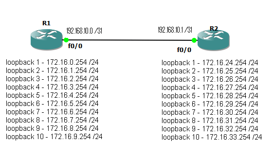
Fig 1

To start with we have two routers connected via a point to point link on interface Fastethernet 0/0. Each also has 10 loop back interfaces configured with various /24 networks configured.

The aim is simple, enable EIGRP with an AS number of 10, form a neighbour relationship between the two routers and update the routing tables so both routers can see / reach all configured networks. Ideal use as few network statements as possible, while remaining as specific as possible as to what networks get advertised. Autosmmorization should also be disabled.

After completing this, a #show ip route, should display something like this.

router1#sh ip route
Codes: C - connected, S - static, R - RIP, M - mobile, B - BGP
D - EIGRP, EX - EIGRP external, O - OSPF, IA - OSPF inter area
N1 - OSPF NSSA external type 1, N2 - OSPF NSSA external type 2
E1 - OSPF external type 1, E2 - OSPF external type 2
i - IS-IS, su - IS-IS summary, L1 - IS-IS level-1, L2 - IS-IS level-2
ia - IS-IS inter area, * - candidate default, U - per-user static route
o - ODR, P - periodic downloaded static route

Gateway of last resort is not set

192.168.10.0/31 is subnetted, 1 subnets
C       192.168.10.0 is directly connected, FastEthernet0/0
172.16.0.0/24 is subnetted, 20 subnets
D       172.16.32.0 [90/409600] via 192.168.10.1, 00:01:01, FastEthernet0/0
D       172.16.33.0 [90/409600] via 192.168.10.1, 00:01:01, FastEthernet0/0
D       172.16.28.0 [90/409600] via 192.168.10.1, 00:01:01, FastEthernet0/0
D       172.16.29.0 [90/409600] via 192.168.10.1, 00:01:01, FastEthernet0/0
D       172.16.30.0 [90/409600] via 192.168.10.1, 00:01:01, FastEthernet0/0
D       172.16.31.0 [90/409600] via 192.168.10.1, 00:01:01, FastEthernet0/0
D       172.16.24.0 [90/409600] via 192.168.10.1, 00:01:01, FastEthernet0/0
D       172.16.25.0 [90/409600] via 192.168.10.1, 00:01:01, FastEthernet0/0
D       172.16.26.0 [90/409600] via 192.168.10.1, 00:01:01, FastEthernet0/0
D       172.16.27.0 [90/409600] via 192.168.10.1, 00:01:01, FastEthernet0/0
C       172.16.8.0 is directly connected, Loopback9
C       172.16.9.0 is directly connected, Loopback10
C       172.16.4.0 is directly connected, Loopback5
C       172.16.5.0 is directly connected, Loopback6
C       172.16.6.0 is directly connected, Loopback7
C       172.16.7.0 is directly connected, Loopback8
C       172.16.0.0 is directly connected, Loopback1
C       172.16.1.0 is directly connected, Loopback2
C       172.16.2.0 is directly connected, Loopback3
C       172.16.3.0 is directly connected, Loopback4

Now to reduce the size of the routing table we can manually summarise the routes. This is carried out under the interface that is sending out the update (in this case it will be fast ethernet 0/0 on each router). Again we want to be as specific as possible. The completed LAB uses multiply summarization statements , this increase the specificity of the summarization at the expense of adding an extra route in to the table. The routing table should now look something like.

router2#sh ip route
Codes: C - connected, S - static, R - RIP, M - mobile, B - BGP
D - EIGRP, EX - EIGRP external, O - OSPF, IA - OSPF inter area
N1 - OSPF NSSA external type 1, N2 - OSPF NSSA external type 2
E1 - OSPF external type 1, E2 - OSPF external type 2
i - IS-IS, su - IS-IS summary, L1 - IS-IS level-1, L2 - IS-IS level-2
ia - IS-IS inter area, * - candidate default, U - per-user static route
o - ODR, P - periodic downloaded static route

Gateway of last resort is not set

 192.168.10.0/31 is subnetted, 1 subnets
C       192.168.10.0 is directly connected, FastEthernet0/0
172.16.0.0/16 is variably subnetted, 15 subnets, 2 masks
C       172.16.32.0/24 is directly connected, Loopback9
D       172.16.32.0/21 is a summary, 00:02:27, Null0
C       172.16.33.0/24 is directly connected, Loopback10
C       172.16.28.0/24 is directly connected, Loopback5
C       172.16.29.0/24 is directly connected, Loopback6
C       172.16.30.0/24 is directly connected, Loopback7
C       172.16.31.0/24 is directly connected, Loopback8
C       172.16.24.0/24 is directly connected, Loopback1
D       172.16.24.0/21 is a summary, 00:02:28, Null0
C       172.16.25.0/24 is directly connected, Loopback2
C       172.16.26.0/24 is directly connected, Loopback3
C       172.16.27.0/24 is directly connected, Loopback4
D       172.16.8.0/24 [90/409600] via 192.168.10.0, 00:02:26, FastEthernet0/0
D       172.16.9.0/24 [90/409600] via 192.168.10.0, 00:02:26, FastEthernet0/0
D       172.16.0.0/21 [90/409600] via 192.168.10.0, 00:02:26, FastEthernet0/0

So the routes from Router 1 are now summarized in to 3 blocks. 172.16.0.0/21 which would include the first 8 networks, plus the 172.16.8.0 and 172.16.9.0 /24 which fall out side the summarization.

Note also the routes to null that have been entered. When you set up a summarization, the router will automatically set up a route to null for that network. The reason for this is that you many not actually have routes to all the subnets for the network you have advertised as a summary. Imagen in the above case there was no loop back 5 and 6 on router 2, so no networks 172.16.28.0 and 172.16.29.0 /24. But the router is still advertising a summary address that includes them. When packet arrive at the router they are routed based on the most specific match. so a packet coming in with a destination address of 172.16.27.59 will match both the following routes.

D 172.16.24.0/21 is a summary, 00:02:28, Null0
C 172.16.26.0/24 is directly connected, Loopback

but because /24 is more specific than /21 the route to the loop back interface will be used. However if there is no more specific route, then the null route will be matched and the packets discarded.

OK I said it was simple and it is. The topology files have both the starting position and my completed example. This is of course not the only solution. You can argue there are neater ways to do it, but I chose to use multiply statements to show how specific networks can be picked and what happens when summary address do not exactly match the networks that are configured.

There will be one more EIGRP Lab coming up that will be more involved and included redistribution of static routes and manual formation on neighbours.

DevilWAH