Lets start with a few links.
Before I learnt about sub-netting, trunk links, access ports, or vlan’s, I started looking in to STP. In fact my introduction to networking went along the lines of. Learn to log on to a 3COM 3300 super stack, assign it an IP address, sort out spanning tree. I had only been working in IT a few months with no previous IT experience when I was given the job of single handily auditing the network and assigning management IP address. At the time the network was a pure Layer 2 single VLAN domain containing around 120 switches spread over 30 buildings. It was during this audit and while setting up a monitoring system that I first notice these network reconfiguration messages that kept popping up, not one to be able to leave alone I looked in to the cause and discovered STP!
I look back on horror as I dread to think how many of those reconfiguration where due to me rebooting a switch, or altering configs. those 3COM’s only ran old CST (802.1d) so every time I was causing up to 50 seconds of down time.. I can only plead ignorance and hope over the past 4 years I have made up for it.
The Spanning Tree Protocol (STP) I think is at its fundamental core, one of the more straight forward networking topics to understand. STP runs at layer 2 and its core function is to prevent loops in the network. Why do we need to prevent loops? Layer 2 has no default inbuilt method to detect if a switch has forwarded the same frame before, so if there are any cabling loops in the network frames will circle endlessly round them, clogging up bandwidth and switch CPU causing poor performance before it all grinds to a halt. At the same time though surely duplicate links are a good thing, if one fails you have one spare?
And this is where all versions of STP come along, by analysing the network as a whole, by sending special packets (bridge discover protocol units BPDU’s) along every link of the network and seeing where the end up, the switches can detect any loops. They will then decided on which links to “block” so that there is only a single complete path across the network. And of course they have there methods to bring back up any of the blocked links in the event any of the primary links they back up should fail.
Before we get in to how this work lets recap the various versions of STP.
CST = 802.1d = Low =SLOW
PVST+ = CISCO = High = SLOW (default)
RSTP = 802.1w = Medium = FAST
PVRST = CISCO = Very High = FAST
MSTP = 802.1s = Medium/High = FAST
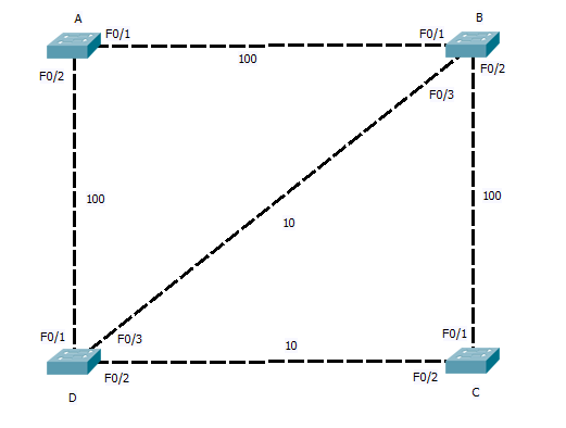
Lets start with PVST+, This differers from CST only in that it runs a separate instance for each VLAN on the switch, this allows load balancing or backup links as we shall see. First lets get a digram up so we have some thing to refer to.
STP works by each switch determining which of its own ports should be forwarding and which should be blocking to insure the network is loop free. Because this is carry out in isolation of what ports other switches and to reduce the time and traffic the network administrator selects a central switch (the ROOT bridge) to act as a reference point for all the other switches. This central switch sends out packets (BPDU’s) on all its ports that are connected. As other switches receive these they note on what ports they are received and then add on the cost of the link. This cost is based on the speed of the link, the following is the table of defaults but these can be tuned if needed.
10Mbs =100100Mbs = 191Gbs = 410Gbs = 2
So our fist step should be to configure what switch is root. This should be your core switch, as this will become the centre of the network with all other switches sending there traffic through it. In the case above we can used Switch A.
Switch_A(config)#spanning tree mode pvstSwitch_A(config)#spanning tree VLAN <ID> root Primary
All done…
Switch A is now the root bridge for the spanning tree on what ever VLAN ID you enter. The keyword root will cause Switch A to listen out on the network for BPDU’s being advertised on the VLAN, each switch advertise its root priority in its BPDU. Switch A will listen for the lowest and then set its own priority lower again. (lowest wins). This only happens as you enter the command. If at a later time another switch is set to a lower priority this switch will take over the root, Switch A will NOT lower its priority again. For this reason there are things like Root Guard that can be enabled.
At the moment the network digram still has loops so how does STP sort it out? Fist of all, ALL ports on A will be in the forwarding state (unblocked), and it is sending out BPDU’s. So lets see how Switch B figures it all out. First it receives a BPDU from Switch A on port F0/1, this has come in over a 100>bs link so it is given a cost of 19, the BPDU on port F0/2 has come via switch D, this will have added a cost of 19 is self as it received it, and Switch B will add a further cost of 100, giving a total root cost of F0/2 as 119. Working the same way F0/3 will be 19 + 100 + 19 = 138.
So the as the lowest cost port becomes the root back to port, Switch B will assign F0/1 as the root port. Repeat for switches C and D, and you will find, for switch C the root port is F0/1 with a cost of 38 and for Switch D it is F0/1 with a cost of 19.
And what now? well now the root ports are sorted out we need to move on to designated ports. These are ports that are connected upstream pointing away from the root. With Switch B and D we see there is a stale mate, both have a 100Mbs link to the root and are connected together by a 10Mbs link. Next STP look towards port priority and as this is the same (both using same port ID) it looks to the MAC address. We will assume Switch B has the lower mac and so it has the higher priority). Switch B will there for place its port F0/3 in to a designated state, Switch D on the other hand seeing Switch B is higher Priority will leave its port with out a STP state. Both Switch B and D will place ports F0/2 that connect to switch C in to the designated state. Switch C already having a root port to B, and seeing that port F0/2 also leads back to the root will again leave this port in a non designated state.
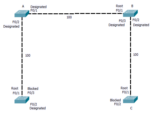
Once the Switches have decided what ports are assigned what states, any port still with out a state and that is receiving the Root BPDU, is put in the blocking state. So we end up with the logical network below.
 As you can see where a link is blocked, one end will be in the designated state on one in the blocking state. In the case of CST and PVST, all BPDU’s are send from the root bridge. In the event of a link failure the affected switch must wait for the Root bridge to send out a BPDU (20 seconds time out by default), Only then does the switch start to listen for BPDU’s on its blocked ports before bringing them up. and this process in its self requires 15 seconds in the listing phase (listing out for the BPDU and building the STP) and a further 15 seconds of learning MAC address before the switch is again forwarding traffic across the back up link. So a total of 50 seconds can elapse.
RSTP and PVRSTP, address this issue, By allowing all switchs in the STP to send and recive BPDU’s, and keeping a note of what are the back up links that are currently being blocked, RSTP and PVRSTP can bring up a failed link with in a second or two. They introduce two new port states. The backup port, which is a second link back to the root. (in the network digram here port F0/3 on switch D and F0/2 on C would be back up ports) And the alternative port, this is when two links connect to the same uplink switch, Imagen switch B and C has two links directly between them, then one would be in the designated port state and the other blocked in the alternative state. By holing a note of the back up links, if the link between Switch D and the root failed, it knows it can bring the link on port F0/3 to switch B up with out danger of causing a loop.
So that’s STP in a nutshell, I will cover MSTP another day, but hopefully there’s enough there to get you head round it, with out load of configuration. All you need to remember is to define your root bridges correctly and insure all you switches are using and support the same STP mode. Once you have that configured correctly then STP will work for you. You then can spend the time tuning it and securing it. Which is a whole other post.

